| |
| |
form·Z resources

|
| |
Creating Stereo Images

With a simple formula, you can use form•Z to create the left
and right images for use in a stereo image. Using special glasses, a stereo
image will appear to have depth when viewed. That is, objects will appear
to come off the page and occupy real world space.
Using the formula below, we can calculate the distance between the left
and right images that make up the stereo composite image. This offset
is what makes the stereo image possible. The formula is as follows:
T1=[p/f] [Dd/(D-d)]
p = horizontal parallax, normally 1/24 of the image width.
f = focal length of the lens. In form•Z this value can be
found in your view parameters
D = distance from the lens to the farthest point
d = distance from the lens to the nearest point
T1 = horizontal distance between the lens axes (or the distance between
the views)
Keep in mind that all of the above variables will need to have the same
unit of measurement, i.e. if the image width is measured in terms of inches,
the "D" values will also need to be measured in terms of inches. With that
said, the first thing you will want to do is determine the final size of
your image so that we can calculate the variable p. For our example, our
final image width is 7", so the p value, which is 1/24 of that, would be
.354 inches.
|
|
Next, set up and save a view at the vantage point that you want the stereo
image to be. Make sure that the view type is perspective. Double click
on the view in the Views palette and take note of the focal length. This
is your f in the formula. In our example, the focal length was 47. (figure
2)
Make this view visible by clicking in the diamond column for the view
in the Views palette. In the model window you should see the camera icon,
the eye point, and the center of interest for the camera.
|
|
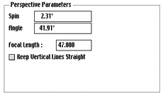
figure
2
|
|
Locate in the view a visible, significant point that is farthest away
from your viewpoint. A significant point would be a point that is part
of the geometry in the general vicinity of the scene. Trees or buildings
in the far background would not qualify. This will be used to calculate
your D value.
With the topological level set to point, select that point of the geometry.
Switch to an orthographic view (axonometric). Locate the selected point
and, using the vector line tool (or the segment tool), point snap to the
selected point. Move the second end point to the eye point of the view
(the beginning of the line of sight). Deselect all points. With the topological
level set to segment, select this new segment and query it. form•Z
will give the coordinates of the end points as well as its length. Take
note of the length. Make sure that your working units correspond to the
units used to compute the p value. This is your D value. In our example,
the D value was calculated to be 3,093.5" (figures 3a, 3b. Note that we
hid most of the geometry for visual purposes.)
|
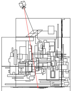
figure 3a |
|
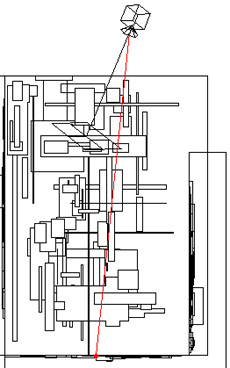
figure
3b
|
| Repeat this step, except instead of using the
farthest point, use the closest significant point. Snap a vector line from
the closest point to the eye point. This is your d value. For our example
the d value was 527". (figures 4a, 4b) |
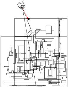
figure
4a |
|
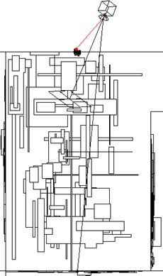
figure 4b
|
|
Plug the numbers into the formula to calculate the T1 distance.
T1 = [.3/47] [ ((3093.5)(527))(3092.5-527)] = 4.
|
|
|
From this formula, we calculated the offset distance to 4". Now we are
going to use this distance to create a second view that is 4" away from
the original view.
In your prompts palette, switch to relative, polar coordinates. In a
top view draw out a vector line perpendicular to the line of sight of
the visible view. The first point should lie on the line of sight as you
are looking at it from a top view. With the second point rubber banded,
position it so that the line is perpendicular. The prompts palette will
display the distance, angle, and the z height. We can tab to the first
field (distance) and input the T1 distance. End the line. This should
give you a line that is perpendicular to the line of sight and has a length
of T1.
(figure 5)
|
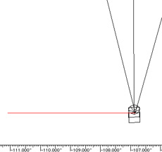
figure 5
|
|
Set the self/copy modifier to one copy and with the move tool click on
the line of sight at the point that it meets the segment you just created.
Move your cursor along the segment, and when the cursor is over the other
end point, click to create a copy of your view. This will give you a view
that is offset from the other at the distance of T1. If you wanted to
have the saved view the center of the left and right images, simply move
the construction segment so that its midpoint lies on the line of sight.
Copy the view to the left and right along this segment, then use these
two new views for the left and right images.
(figure 6)
|
|
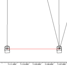
figure 6
|
Render the left and right views and save them.
In order to create a stereo image from these two views, they will need to
be processed by a company that makes stereo images, such as The Slide Factory.
They will take your two images and create a stereo composite that, when
viewed, will appear to have depth and occupy space. For more information
on this topic, you may visit the website of San Francisco Imaging Services
at www.sfimaging.com.
|
| |
|
|